VLAN Trunking Concepts
VLANS Configs Explained
Virtual LAN Concepts
LANs designed ti use VLANS significantly improves the LAN by limiting the number of hosts that waste efforts processing unnecessary broadcasts.
Purpose for creating smaller broadcast domains;
- to reduce CPU overhead by reducing the number of devices that receive broadcast frames.
- to reduce security risks by reducing the number of hosts that receive copies of frames that the switch flood.
- to improve security for hosts that send sensitive data.
- to create more flexible designs that group users by department
- to solved problems more quickly, because the failure domain for many problems is the same set of devices as those in the same broadcast domain.
- to reduce the workload for the STP by limiting a VLAN to a single access switch.
When using VLANs in networks that have interconnected switches, the switches need to use VLAN trunking on those interconnected links. When implementing VLAN trunking it causes the switches to use a process of VLAN tagging, which happens when the sending switch adds another header to the frame before sending it over the trunk. The header that is attached is known as the VLAN ID field so that the sending switch can associate the frame with a particular VLAN ID and the receiving switch knows with VLAN the frame belongs to.
802.1Q VLAN Trunking Protocols
802.1Q inserts an additional 4-byte tag into the original frame's Ethernet header but only the 12-bits are actually the VLAN ID.
Voice VLANs Explained
For IP telephony designs administrators should place phones in one VLAN and PC's in a different VLAN. Traffic coming from the Voice VLAN forwards the phone's traffic as tagged frames. CDP or LLDP must be enabled on an interface for the voice access port to work with phones that have an embedded switch.
Use vlan <vlan-id> command to create the voice vlan
Use interface <type number> command to configure interface
Use switchport mode access to make port always operate as access port
Use switchport mode access vlan <vlan-id>, to define data vlan, typically native
Use switchport mode access voice vlan <vlan-id>, to define voice vlan
How EIGRP mechanisms are used during path computations for accelerating convergence and increasing scalability in an EIGRP network.
EIGRP takes advantage of the deficiencies with other distance-vector routing protocols by utilizing features as unequal-cost load balancing and rapid convergence. Most distance-vector routing protocols use hop count for routing decisions and do not take into account link speed and delay metrics. To identify network paths and fast convergence EIGRP uses a diffusing update algorithm DUAL. Autonomous Systems Routers can run multiple EIGRP processes which operates on an autonomous system representing a common routing domain. Each process correlates to a specific autonomous system and maintains a separate topology table.
IPv6 Addressing + Host Forwarding Determination IPv6 addressing is made up of two parts: the first 64 bits usually represent the subnet prefix , the last 64 bits usuallly represent the interface ID. Typically manual configuration of IPv6 addressing is not advised therefore should be auto-generated or based on IEEE EUI-64 standards. When IPv6 hosts need to communicate with another host it compares its subnet bits with the destination IP address, if subnet bits match the hosts communicate directly, if they differ hosts communicate through the default gateway. If the subnet ID bits are identical the host creates a frame with is own source MAC address and sends the frame directly to the destination MAC address, otherwise it sends the frame to the destination MAC address of the default gateway. IP address verification on PC (Windows) issue command: ipconfig IP address verification on Cisco IOS issue command: show ip interface interface_type interface_number Assigning IPPv6 Addresses to Hosts IPv6 Unicast Address Types Global Unicast = Public Unique Local Unicast = Private Link-Local = Local IPv6 uses NDP (Neighbor Discovery Protocol) for hosts to dynamically learn their IPv6 settings. Options available are Stateful DHCP and Stateless Address Autoconfigurattion (SLAAC). Although Stateful DHCPv6 share the same general principles as DHCPv4 Stateful DHCPv6 does not offer hosts default information, handing this off to NDP for local routers to identify themselves. SLAAC does not require a stafeful server to lease the IPv6 address and document state information about host addressing. The process utilizes NDP so host can learn the information from any router on the link, gathering prefix, prefix length and defasult router address. SLAAC rules are used to build the rest of the host address generated randomly or using EUI-64, then stateless DHCPv6 is used to provide DNS server information. EUI-64 The hosts 48 bit MAC address is used to construct the Interface ID of the client, which is split in half and the hex value FFFE is placed in the center. The seventh bit from the left is inversely flipped to a 1 or 0 depending on the original bit. The interface ID equates to 64 bits in total after the conversion is complete. MAC Address 0800:275D:06D6 Becomes MAC Address 0A00:27FE:FE5D:06D6 Enabling SLAAC on Router Interface Interface Configuration Mode, issue following commands: R1(config)# interface gi0/0 R1(config-if)# ipv6 unicast-routing -- Enables IPv6 routing R1(config-if)# ipv6 address autoconfig -- Enables SLAAC manually on an interface Router Advertisements by default are generated only on interfaces that are enabled for IPv6 routing and are not suppressed on the interface. In addition SLAAC only works if a router is using prefix /64. DHCPv6 Operation Process 1. SOLICIT: Clients send a solicit message to locate DHCPv6 server using multicast address FF02::1:2 (All-DHCPv6-Server multicast address) Process 2. ADVERTISE: Servers respond to SOLICIT messages offering addressing information to the client using unicast ADVERTISE messages. Process 3. REQUEST: Clients confirm the addresses provided and sends this message to the server. Process 4. REPLY: Servers finalize the process with this message.
IPv4 Addressing + Host Forwarding Determination IPv4 addressing is made up of three parts: a network /subnet portion and a host portion, which it is highly important that all host in the same subnet share the same network/subnet portion. If these portions are not the same host devices may address the Layer 2 frame incorrectly forwarding packets in the wrong direction. When hosts need to communicate with other hosts a DNS lookup is performed for the destination host IP address. The source host must determine if the destination host is located in the same subnet in order to correctly forward the frame either to the MAC address of the destination host or default gateway. If the subnet ID bits are identical the host creates a frame with is own source MAC address and sends the frame directly to the destination MAC address, otherwise it sends the frame to the destination MAC address of the default gateway. IP address verification on PC (Windows) issue command: ipconfig IP address verification on Cisco IOS issue command: show ip interface interface_type interface_number DHCPv4 + Relay Agent Process DHCP services allow for DHCP clients to acquire 4 important network components such as IP address, netmask, default gateway IP address and DNS IP address with exchange message process Discover, Offer, Request, Acknowledgement. DHCP clients communicate by sending a broadcast message of DHCPDISCOVER to destination IP 255.255.255.255 along with destination MAC FFFF:FFFF:FFFF:FFFF in efforts to locate a DHCP server. The client source IP address is 0.0.0.0 and its own MAC address. DHCPDISCOVER messages are sent as a broadcast although broadcasts cannot cross router boundaries. So in this case, if a host resides on a different network than the DHCP server, the default gateway of the host will need to be configured as a DHCP relay agent. This enables broadcast packets to be forwarded as unicast packets to the DHCP server. DHCP Relay Agent Commands in Brief Global configuration Mode, issue command: service dhcp -- Enables DHCP service on router for DHCP services to function Interface Configuration Mode, issue command: ip helper-address ip_address -- Specifies the IP address of the DHCP server, command must be configured on interface receiving the DHCPDICOVER messages from the hosts. DHCPv4 Messages Types DHCPDISCOVER Host message to locate DHCP server using, UDP port 67 DHCPOFFER DHCP server message in response to DHCPDISCOVER, using UDP port 68 DHCPREQUEST Host message from host to DHCP server requesting IP addressing information received from DHCPOFFER reply DHCPACK DHCP server message to a client including IP configuration parameters DHCPDECLINE Message from client informing DHCP server that an IP address is already in use DHCPNAK DHCP server message declining client IP configuration information DHCPRELEASE Client message informing DHCP server to release its DHCP lease DHCPINFORM Message from client requesting IP configuration information for a remote client attaching to an access server. Potential DHCP Troubleshooting Issues A router not forwarding broadcasts verify DHCP relay agent is configured if DHCP client and server are on different subnets DHCP pool out of IP addresses Misconfiguration Duplicate IP addresses Redundant services not communicating If DHCP interserver communication fails, DHCP servers hand out overlapping IP addresses The pull nature of DHCP DHCP servers have no ability to initiate modifications in client IP address after the client acquires an IP address, clients only pull information from DHCP server. Interface not configured with IP in DHCP pool DHCP Troubleshooting Commands in Brief show ip dhcp conflict -- output indicates duplicate IP addresses on a network show ip dhcp binding -- output indicates that IP addresses assigned to DHCP client clear ip dhcp binding * -- command to release DHCP leases debug ip dhcp server events -- output shows updates to the DHCP database debug ip dhcp server packet -- output shows DHCP messaging information Odom, Wendell (2017.) (Cisco CCNA Routing and Switching, Official Cert Guide.)
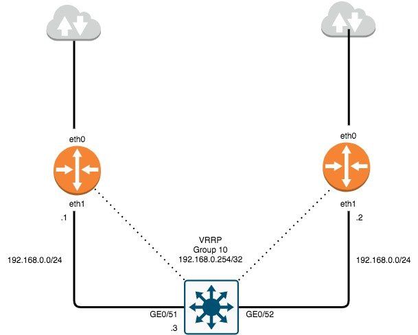
VRRP is part of the First-Hop Redundancy Protocol family that allows the continuance of network traffic to be processed and forwarded when a router becomes unavailable. VRRP Virtual MAC: 00:00:00:00:XX, "XX" is defined by group number. VRRP Multicast Address: 224.0.0.18 VRRP Virtual Address: Address to be utilized as default gateway for hosts. VRRP Configuration Prerequisites 1. Ensure there is a route defined to L3 switch where vlan's reside and can be reached from native subnet. 2. Ensure L3 switch has a default-gateway to reach router IP if uplink to router is NOT a routed port. 3. Ensure default-gateway is defined as the VRRP virtual-address for hosts within native vlan. 4. If using recursive DNS, ensure DNS address is defined as the VRRP virtual address for hosts within native vlan. NOTE: Prerequisites are also required on VRRP router acting as backup. EdgeOS VRRP Configuration and Authentication 1. # set interfaces ethernet eth1 address 192.168.0.0/24 # edit interfaces ethernet eth1 # set vrrp vrrp-group 10 description ALL_VLAN_VRRP # set vrrp vrrp-group 10 virtual-address 192.168.0.254/32 # set vrrp vrrp-group 10 advertise-interval 3 # set vrrp vrrp-group 10 authentication type ah # set vrrp vrrp-group 10 authentication password ******* # compare # commit; save EdgeOS VRRP Verification 1. Verify VRRP is activated on the correct interface. # show configuration ethernet eth1 { address 192.168.0.1/24 description native_vlan duplex auto speed auto vrrp { vrrp-group 10 { advertise-interval 3 authentication { password **************** type ah } preempt true priority 200 virtual-address 192.168.0.254/32 2. Verify VRRP virtual address is attached to correct interface. # show interfaces ethernet eth1 brief Codes: S - State, L - Link, u - Up, D - Down, A - Admin Down Interface IP Address S/L Description --------- ---------- --- ----------- eth1 192.168.0.1/24 u/u native_vlan 192.168.0.254/32 3. Verify VRRP operation status and correct router master election. # run show vrrp Physical interface: eth1, Source Address 192.168.0.1 Interface state: up, Group 10, State: master Priority: 200, Advertisement interval: 3, Authentication type: ah Preempt: true, VIP count: 1, VIP: 192.168.0.254/32 Master router: 192.168.0.1 Last transition: 42m30s

1. Problem Isolation and Documents By taking what you know about a possible issue and confirming there is a problem you must discover which devices and cables could be part of the problem and which ones are not part of the problem. Documenting your findings while isolating your problems will help with unveiling what was the specific problem. 2. Resolve or Escalate Problem isolation typically uncovers root causes - resolving issues means finding the root cause of the issue and fixing that issue. If you cannot find the root cause or fix the problem must be escalated. 3. Verify or Monitor After you have fixed an issue now you must verify that the fix actually worked. This could mean verifying with certain commands or monitoring over a period of time, especially when the cause of the root problem was unknown. Common Layer 1 Problems An interface is considered working when the status is in an up/up state. Switches have interface counters which can help identify issues that occur wile in the connected state. If physical transmissions have problems the receiving device may receive frames where the bits has changed in value and the frames does not pass error detection. The receiving device discards the frame and counts it as some input error. Runts: Frames that did not meet the minimum frame size requirement(64 bytes, including the 18-byte destination MAC, source MAC, type, and FCS). Can be caused by collisions. Giants: Frames that exceed the maximum frame size requirement. Input Errors: A total of many counters, including runts, giants, no buffer, CRC, frame, overrun, and ignored counts. CRC: Received frames that did not pass the FCS math; can be caused by collisions. Frame: Received frames that have an illegal format, for example, ending with a partial byte; can be caused by collisions. Packets Output: Total number of packets (frames) forwarded out the interface. Output Errors: Total number of packets that the switch port tried to transmit, but for which some problem occurred. Collisions: Counter of all collisions that occur when the interface is transmitting a frame. Late Collisions: The subset of all collisions that happen after the 64th byte of the frame has been transmitted. Late collisions today often point to a duplex mismatch.
Auto-Negotiation Explained IEEE auto-negotiation results when both nodes use the process. While it is possible to disable auto-negotiation on links, mistakes can happen resulting in the link nor working at all or may work poorly. The most classic and common error of predefining interface speed and duplex is a speed/duplex mismatch. this can be corrected by ensuring both speed and duplex settings match on both ends of the link or allowing one end to perform auto-negotiation based on the settings at the other end of the link. Port Security Explained - Port Security is used to restrict an interface so that only the expected devices can process frames, its intent is to reduce exposure to attacks. Port Security identifies devices solely by the source MAC address of the incoming frame. If an interface was configured with port security it would examine the MAC address to decide if the device was allowed to transmit frames into that port. Each port has a maximum number of allowed addresses which means it has no restrictions on being configured on trunk ports with a specified number of allowed devices (MAC addresses). If a new source MAC address arrives that is inappropriate for the configured settings a violation has occurred. The switch then discards all future incoming traffic on that part. Port Security Modes Before port security can implemented VTP mode must be disabled and the port which will be used for port security requires the port to be configured as an access or trunk port. The default action for a violation is to shutdown the interface. Enable port security with the following commands: switchport mode access | trunk switchport port-security - configuration with defaults Override Default Configuration + switchport port-security maximum - override the default maximum number of allowed MAC addresses associated with the interface. + switchport port-security violation protect | restrict | shutdown - default action to take upon security violation + switchport port-security mac-address sticky -tells the switch to dynamically learn MAC addresses. + switchport port-security mac-address predefine any allowed source MAC addresses, command can be used multiple times to define more than one MAC address.
How IP Hosts expects IP addresses to be grouped into Networks or Subnets. Addresses in a single IP network have the same numeric value in the first part of all addresses in a network, with this said... a. All IP addresses in the same group must not be separated from each other by a router. b. IP addresses separated from each other by a router must be in a different group. How Routers choose to Forward Packets to the Final Destination *Two-step process on how routers route* a. If the destination IP address is in the same IP subnet, the network device sends the packet directly to that destination. b. Otherwise, he network device will send the packet to its default gateway which is typically the routers interface on the same subnet as the host. Router Forwarding Logic A router receives data link frames addresses to that routers data link address, when this happens a router needs to process the contents of the frame when it arrives. a. Routers use the data link Fram Check Sequence (FCS) field to ensure no error have occurred, if any errors have occurred the router discards the frame. If no errors have occurred the router discards the old data link header and trailer leaving only the IP packet. b. The router then compares the IP packets destination IP address to the routing table to discover the route that best matches the destination address. Routers also identifies the outgoing interface and possibly the next hop router IP address. c. The router then encapsulates the IP packet inside a new data-link header/trailer then forwards the frame. Goals of Routing Protocols The forwarding process when routing depends on having an accurate and up-to-date routing table. Routing protocols use methods to teach and learn routes. a. To dynamically learn and fill the routing table with a route to each subnet in the internetwork. b. To place the best route in the routing table, if more than one route exists. c. To remove routes from the table when they are no longer valid. Then update the routing table when a route becomes available. d. To converge quickly when replacing lost routes or adding new ones. e. To prevent routing loops. Learning Routes to Add to Routing Table a. Routers add routes to its routing table for each subnet directly connected to the router. b. Routing protocols tell its neighbors about the routes in its routing table including directly connected routes and learned routes. c. After learning new routes, routers add these routes to its IP routing table with next-hop router, typically being the neighbor from which the route was learned
Useful command reference to configure vlans within Cisco switches. Switch EXEC Commands + show interfaces interface-id switchport - lists information about any interface regarding administrative settings and operational state + show interfaces interface-id trunk - lists information about all operational trunks including the list of vlans that can be forwarded over the trunk + show vlan [brief | id vlan-id | name vlan-name | summary] - lists information about the vlan + show vlan [vlan] - displays vlan information + show vtp status - lists vtp configuration and status information Switch Global Configuration Commands + vlan vlan-id - creates the vlan and puts the cli into vlan config mode + [no] shutdown vlan vlan-id - command that has the same effect as the [no] shutdown vlan mode subcommands + vtp mode { server | client | transparent | off} - command that defines the vtp mode Switch Subcommands + name vlan-name - vlan subcommand that names the vlan + [no] shutdown - vlan mode subcommand that enables (no shutdown) or disables (shutdown) the vlan + switchport mode {access | dynamic | auto | desirable | trunk} - interface subcommand that configures the trunking administrative mode on the interface + switchport mode access vlan vlan-id - interface subcommand that statically configures the interface into that one vlan + switchport trunk encapsulation {dot1q | isl | negotiate} - interface subcommand that defines which type of trunking to use, assuming that trunking is configured or negotiated + switchport trunk native vlan vlan-id - interface subcommand that defines the native vlan for a trunk + switchport nonegotiate - interface subcommand that disables the negotiation of vlan trunking + switchport voice vlan vlan-id - interface subcommand that defines the voice vlan on a port, meaining that the switch uses 802.1q tagging for frames in this vlan + switchport mode allowed vlan {add | all| except | remove} - interface subcommand that defines the list of allowed vlans

Cisco still remains to be a major player in the world of networking with recent updates in all certification paths. They have extended new knowledge and commands to further simplify troubleshooting and configurations. These references should help beginners and mid-level network administrators. Help Commands ? = help for all commands available in specified mode. command ? = lists text to describe all the first parameter options for the command. com? = list of commands that start with com. command parm ? = lists all parameters beginning with the parameter typed so far. command parm = tab causes IOS to spell out the rest of the word. command parm1 ? = space lists all the next parameters and gives brief explanation. User Mode Commands Show Command - lists currently known facts about the devices operational status. + show running-config = lists the contents of the running-config file. + show startup-config = lists the contents of the startup-config file. + show interfaces status = lists one line per interface on the switch, with basic status and operational information. + show mac address-table = shows all MAC table entries of all types. + show mac address-table dynamic = shows all dynamically learned MAC table entries. + show mac address-table static = shows all statically assigned MAC table entries. + show mac address-table secure [interface interface-id ] = lists MAC addresses defined or learned on port configured with port security. + show port security = list one lone per interface summarizing port security settings on which it is enabled. + show port-security interface t ype number = lists an interface's port secuirty configuaration settings and security operational status. + show mac address-table dynamic vlan vlan-id = shows all dynamically learned MAC table entries in that vlan. + show mac address-table dynamic mac-address = show the dynamically learned MAC table entry with that MAC address. + show MAC address-table dynamic [interface interface-id] = show all dynamically learned MAC address entries associated with that interface. + show mac address-table count = shows the number of entries in the MAC table and total number of remaining empty slots in the MAC table. + show mac address-table aging-time = shoe the global and per VLAN aging timeout for inactive MAC table entries. + clear mac address-table dynamic = empties the MAC table of all dynamic entries.enable = moves user from user mode to enable mode and prompts for a password if one is configured. + show dhcp lease = list information acquired as a dhcp client. + show ip ssh = lists status information for the ssh server. + show ssh = lists status information for current ssh connections into and out of the local switch. Console/VTY Line Mode Commands + login = line (console and vty) configuration mode, tells IOS to prompt for a password (no password). + login local = tells IOS to use username secret, checked against locally configured username in global configuration mode. transport input { telnet | ssh | both | none } = defines whether telnet/ssh access is allowed into the device, both accessible by default. Interface Mode Commands + ip address ip-address subnet-mask = VLAN interface mode, statically configures ip address and mask. + ip address dhcp = VLAN interface mode, configures dhcp client to discover ipv4 address, mask and default-gateway. + speed { 10 | 100 | 1000 | auto } = manually sets the speed to the listed speed, auto automatically negotiates the speed. + duplex { auto | full | half } manually sets the duplex. + switchport mode { access | trunk } = tells the switch to operate as an access port or trunk port. + switchport port-security mac-address mac-address = statically allows a specific MAC address on the interface. + switchport port-security mac-address sticky = learns MAC address on the interface and adds to secure MAC addresses. + switchport port-security maximum value = sets the maximum number of static secure MAC addresses . to be assigned to a single interface. Configuration Commands + line console 0 = changes the context to console configuration mode. + line vty 1st-vty last-vty = changes the context to vty configuration mode. + interface type port-number = changes the context interface mode --interface FastEthernet 0/1. + interface vlan number = changes the context to VLAN interface mode, allows the configuration of ip address. + ip default-gateway = configures default gateway ipv4 address. + ip domain-name = sets the domain name of the network + ip name-server server-ip-1 server-ip-2 = configures ipv4 address of dns servers. + password pass-value = line (console and vty) mode, sets the password required on that line for login. + username name secret pass-value = used when login local has line config command has been used for user authentication. + hostname name = sets this switch's hostname, which is also used as the first part of the switch's command prompt. + crypto key generate rsa [modulus] 360-2048 = creates and stores the keys required for SSH + exit = moves back to the next higher mode in configuration. + CTRL+Z = does the same thing as the end command. EXEC Command Reference + [no] debug all / undebug all = enable mode EXEC command to disable all currently enabled debugs. + reload = enable mode EXEC command that reboots the switch or router. + copy running-config startup-config = enable mode EXEC command that saves the active config. + copy startup-config running-config = enable mode EXEC command that merges the startup-config file with the currently active config file in RAM. + write erase = enable mode EXEC commands erase the startup-config file. + erase startup-config = " " + erase nvram = " " + quit = EXEC command that disconnects the user from the CLI session. + configure terminal = Enable mode command that moves the user into configuration mode.